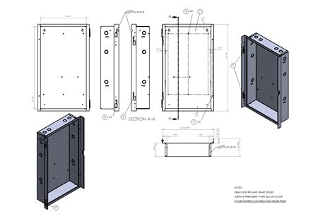
dimension sheet metal drawing Dimension the part in a single direction wherever possible. Because of the sequential nature of the forming process, and the fact that dimensional variation is introduced at each bend, . Metal fencing requires a considerable investment of material and skill to erect—particularly if the fencing is designed to be sympathetic with traditional architecture. Here's a look at the various materials and designs available for traditional metal fencing. Forged and fabricated steel fencing from Bill's Custom Metal Fabrications.
0 · sheet metal layout drawings
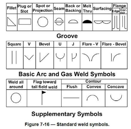
1 · sheet metal drawing symbols
2 · sheet metal dimensioning standards
3 · sheet metal dimensioning guidelines
4 · sheet metal diagram fabrication
5 · sheet metal design basics
6 · sheet metal basic drawing
7 · sheet metal basic design guidelines
Sheet metal is metal formed into thin, flat pieces, usually by an industrial process. Thicknesses can vary significantly; extremely thin sheets are considered foil or leaf, and pieces thicker than 6 mm (0.25 in) are considered plate, such as plate steel, a class of structural steel. Sheet metal is available in flat pieces or coiled strips.

Reading a sheet metal drawing involves identifying the details of the design of sheet metal parts, such as dimensions, geometry, material specifications, and any special requirements. Meanwhile, detailing this . Sheet metal drawings provide detailed dimensions, tolerances, and material requirements, helping manufacturers accurately understand design intent and produce products that meet specifications. Part sketches should be dimensioned and constrained in a manner that allows them to be easily modified without deforming the part and causing rebuild errors. Design intent .
Dimension the part in a single direction wherever possible. Because of the sequential nature of the forming process, and the fact that dimensional variation is introduced at each bend, . This video demonstrates how to properly dimension a sheet metal layout technical drawing. It reviews general dimension standards as well as requirements for.Sheet metal design guidelines are followed for sheet metal enclosure and part design to ensure the first time right product and reduce cost.
Knowing how to dimension a part in a drawing makes metal fabricating that part much easier. Drafting, which you could call the “language of industry,” is not complete without dimensioning, writes Mark Schwendau. .In CAD drafting for sheet metal fabrication, dimensioning involves precisely annotating the size and location of features on 2D drawings or 3D models, crucial for part fit and function. This .
In this article, we’ll discuss how you can make sure you create technically correct and more manufacturable sheet metal drawings. The most important general considerations to make in design are precision in terms of .A fully dimensioned sheet metal drawing includes dimensions for all bends, holes, countersinks, flanges, and other formed features (such as hems and curls, ribs, dimples, etc.). It is a best practice to dimension to virtual intersection points and show included bend angles. Reading a sheet metal drawing involves identifying the details of the design of sheet metal parts, such as dimensions, geometry, material specifications, and any special requirements. Meanwhile, detailing this information requires a series of .
sheet metal layout drawings
Sheet metal drawings provide detailed dimensions, tolerances, and material requirements, helping manufacturers accurately understand design intent and produce products that meet specifications. Part sketches should be dimensioned and constrained in a manner that allows them to be easily modified without deforming the part and causing rebuild errors. Design intent should be considered when creating part sketches.Dimension the part in a single direction wherever possible. Because of the sequential nature of the forming process, and the fact that dimensional variation is introduced at each bend, dimensioning in a single direction parallels the process and helps to . This video demonstrates how to properly dimension a sheet metal layout technical drawing. It reviews general dimension standards as well as requirements for.
Sheet metal design guidelines are followed for sheet metal enclosure and part design to ensure the first time right product and reduce cost. Knowing how to dimension a part in a drawing makes metal fabricating that part much easier. Drafting, which you could call the “language of industry,” is not complete without dimensioning, writes Mark Schwendau. Getty Images. One of the most important aspects of drafting parts is dimensioning.
In CAD drafting for sheet metal fabrication, dimensioning involves precisely annotating the size and location of features on 2D drawings or 3D models, crucial for part fit and function. This includes
In this article, we’ll discuss how you can make sure you create technically correct and more manufacturable sheet metal drawings. The most important general considerations to make in design are precision in terms of product design and the need to design for manufacturability.A fully dimensioned sheet metal drawing includes dimensions for all bends, holes, countersinks, flanges, and other formed features (such as hems and curls, ribs, dimples, etc.). It is a best practice to dimension to virtual intersection points and show included bend angles. Reading a sheet metal drawing involves identifying the details of the design of sheet metal parts, such as dimensions, geometry, material specifications, and any special requirements. Meanwhile, detailing this information requires a series of .
Sheet metal drawings provide detailed dimensions, tolerances, and material requirements, helping manufacturers accurately understand design intent and produce products that meet specifications. Part sketches should be dimensioned and constrained in a manner that allows them to be easily modified without deforming the part and causing rebuild errors. Design intent should be considered when creating part sketches.
Dimension the part in a single direction wherever possible. Because of the sequential nature of the forming process, and the fact that dimensional variation is introduced at each bend, dimensioning in a single direction parallels the process and helps to . This video demonstrates how to properly dimension a sheet metal layout technical drawing. It reviews general dimension standards as well as requirements for.
sheet metal drawing symbols
Sheet metal design guidelines are followed for sheet metal enclosure and part design to ensure the first time right product and reduce cost. Knowing how to dimension a part in a drawing makes metal fabricating that part much easier. Drafting, which you could call the “language of industry,” is not complete without dimensioning, writes Mark Schwendau. Getty Images. One of the most important aspects of drafting parts is dimensioning.In CAD drafting for sheet metal fabrication, dimensioning involves precisely annotating the size and location of features on 2D drawings or 3D models, crucial for part fit and function. This includes

godwin marine mobile welding & metal fabrication
good cnc machined parts factories
Steel Poles. Steel utility poles have become increasingly popular in recent years due to their strength, durability, and low maintenance requirements. Steel poles can also be more easily recycled than wood poles. These poles are made from galvanized steel, which provides excellent resistance to corrosion and extends the poles’ service life .
dimension sheet metal drawing|sheet metal basic design guidelines