cnc machine tool work offset error compensation method The proposed model-based error compensation method is simple enough to be implemented in five-axis CNC machine tools. Production results exhibit effective compensation . When were CNC machines invented? In 1952, a research team at the Massachusetts Institute of Technology (MIT) developed the first prototype CNC milling machine with J.F. Reintjes. The first commercially available CNC machine — the Cincinnati Milacron Hydrotel — came shortly after.
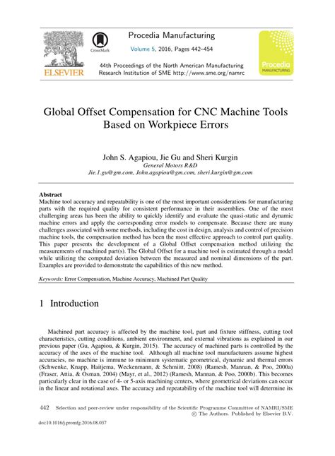
0 · Global Offset Compensation for CNC Machine Tools Based on
1 · Global Offset Compensation for CNC Machine Tools Based
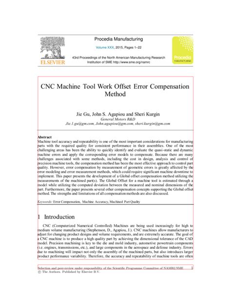
2 · CNC machine tool work offset error compensation method
3 · CNC machine tool work offset error compensation method
4 · (PDF) Global Offset Compensation for CNC Machine Tools
5 · (PDF) Global Offset Compensation for CNC Machine
Most cnc milling parts products boast high quality and low MOQs with direct prices from factory, covering customized cnc lathes and turned aluminum or copper parts, 316 stainless steel threaded insert cnc turning parts, and so on.
An effective static/quasi-static error compensation system composed of an element-free interpolation algorithm based on the Galerkin method for error prediction, a recursive .

3 axis cnc billet rapid trochoidal cool part closeup video
The proposed model-based error compensation method is simple enough to be implemented in five-axis CNC machine tools. Production results exhibit effective compensation . To enhance the machine tool accuracy, the Global offset method is developed for compensating the five-axis machine tool errors based on the measurement results of one or . This new automated compensation method for machine tools is based on the dimensional measurements of identical part(s) in a CMM (Coordinate Measurement Machine); .

Global Offset Compensation for CNC Machine Tools Based on
This paper presents the development of a Global Offset compensation method utilizing the measurements of machined part (s). The Global Offset for a machine tool is estimated through a model.This new automated compensation method for machine tools is based on the dimensional measurements of identical part(s) in a CMM (Coordinate Measurement Machine); it estimates .
This new automated compensation method for machine tools is based on the dimensional measurements of identical part(s) in a CMM (Coordinate Measurement Machine); it estimates .This paper presents the development of a global offset compensation method utilizing the measurements of the machined part(s). The global offset for a machine tool is estimated .Journal of Machine Engineering, 2019, Vol. 19, No. 4, 70–81 ISSN 1895-7595 (Print) ISSN 2391-8071 (Online) Received: 12 November 2019 / Accepted: 03 December 2019 / Published online: 20 December 2019 machine tool error, compensation, control system Pawel MEDYK1* Jerzy JEDRZEJEWSKI1 Marcin KASPRZAK1 CNC MACHINE TOOL ERROR COMPENSATION . Current tool path computation in the CAM algorithms approximates the surface by piecewise linear interpolation. In the case of three-axis machining on a CNC machine the tool will exactly reproduce.
Global Offset Compensation for CNC Machine Tools Based
CNC machine tool work offset error compensation method
Though this topic does not find mention in most undergraduate manufacturing engineering texts, except (Tlusty, 1999), it has a place in the modern manufacturing curriculum at the undergraduate level, being of utmost importance in manufacturing process equipment design.Here, we present a method which we have successfully used to introduce the subject .

machine tools, the compensation method has been the most effective approach to control part quality. This paper presents the development of a Global Offset compensation method utilizing the .
Anik Manglik et al 130 configurations involve a double turntable which rotates the work-piece. An example is a θx –rotation of the part, followed by a θz –rotation, X-translation, Y-translation and a final Z-translation (RRTTT). Other common configurations are RTTTR and TTTRR.
The global offset for a machine tool is estimated through a model while utilizing the computed deviation between the measured and nominal dimensions of the part. Furthermore, the paper presents several other compensation concepts supporting the global offset method. The strengths and limitations of all compensation methods are also discussed.Semantic Scholar extracted view of "Global Offset Compensation for CNC Machine Tools Based on Workpiece Errors" by J. Gu et al. . and the essence of the offset curve is a method of path modification, which means that the general formula for offset compensation of plane curve is obtained through normalization. . CNC machine tool work offset . ISO-230-6, Test code for machine tools Part 6: Determination of positioning accuracy on body and face diagonals (Diagonal displacement tests) - First edition. This new automated compensation method is based on the offline part dimensional measurements in a CMM; it estimates the offsets in the WCS (Work Coordinate System) to compensate the machine tool errors including the fixture and table/pallet errors together with the tool length, some of the dynamic errors due to part clamping, tool deflections .
For manually operated machine tools, the accuracy of the machine tool structure limits the accuracy of the parts produced. Such is not necessarily the case with computer numerically controlled (CNC) machinecompensation implementing on machine tools with Siemens 840D CNC systems, which communicates with CNC system by the DRF offset function and substitutes for electronic
[email protected] +86 155 8824 1112; Home; Product. CNC LATHE MACHINE. CNC FLAT BED LATHE MACHINE; CNC SLANT BED LATHE MACHINE Referring to Figs. 5b and 6b, given K-fold number is 3, when tanθ is less than 1, Nor.(MSE(KCV)) grows or diminishes gradually.When tanθ is greater than 1, Nor.(MSE(KCV)) grows rapidly, and the model begins to lose excessive MSE(KCV), causing the model to tend to be underfitting.Thus, when tanθ equals 1, it is set to be the critical point of Nor.(MSE(KCV)).
The » » » » « « « « ,,,,, ) ) This paper presents a review of the latest research activities and gives an overview of the state of the art in understanding changes in machine tool performance due to changes in thermal . This new automated compensation method for 5-axis machine tools is based on the dimensional measurements of identical parts in a CMM (Coordinate Measurement Machine); it estimates the offsets in the WCS (Work Coordinate System) to compensate the machine tool errors including the fixture and table/pallet errors together with some of the dynamic .
For example: G43 Z H or G44 Z H. The H represents the tool length compensation offset number, ranging from H00 to H99. Example of tool length compensation with G43 code (3-aix milling machine):; Define tool length compensation parameter N10 LLENGTH=-2; Tool tip length compensation, assumed 2mm in advance; Start milling first surface
CNC machine tool work offset error compensation method
2.1 Configuration of a 5-axis machine tool. As depicted in Fig. 1, an XFYZBA-type five-axis machine tool with a universal head is considered in this paper, and it is composed of three linear axes (X, Y, and Z) and two rotary axes (A and B).It should be emphasized that the compensation method is also fit for machine tools with other structures. Different approaches have been applied to manufacturing face gears, including shaping, hobbing, grinding, cutting, etc. The shaping method was used as a theoretically fundamental way to design and manufacturing of face gears, of which the face gear tooth surface is usually designed as the envelope surface of a shaper cutter [3].Wang et al. [4] proposed a . of this work must maintain attribution to the author(s) and the title of the work, journal citation and DOI. Content from this work may be used under the terms of the Creative Commons Attribution 3.0 licence.Any further distribution of this work must maintain attribution to the author(s) and the title of the work, journal citation and DOI.
2. Tool offset compensation. The meaning of tool offset. Tool offset is a function to compensate the difference between the assumed tool length and the reference tool length. The CNC system of the lathe stipulates that the X-axis and the Z .
As shown in Fig. 1, the three-axis vertical CNC machining center can be regarded as a combination of multiple rigid bodies according to the theory of multibody system kinematics.It includes the bed (body 0), X-axis moving parts (body 2), Y-axis moving parts (body 3), Z-axis moving parts (body 4), and spindle rotating parts (body 5).In addition, Fig. 1 also includes a . then you add cutter compensation for the radius of the endmill -example program: . FROM OFFSET TABLE HELD IN CNC COMPUTER- TOOL ADJUSTS TO THE LEFT (OUTSIDE) OF THE PART LINE (G41) ON ITS WAY TO (X0 Y0) x0 y1 x1 y1 x1 y0 x0 y0 X-1 Y0 G40 (TURNS OFF CRC IN A NON-CUTTING . due to spring in the machine, work and . The coordinate origin offset will make the CNC machine tool work in the new coordinate system by changing the relative distance between the mechanical coordinate origin and the reference point of the machine tool.
Investigate a numerical compensation method of elastic deformations in CNC machine tools integrating geometrical, kinematic, dynamic, and thermal errors by virtual elastic models and environmental temperature sensors. Demand in further development of ISO 230—test code for machine tools under dynamic loads and unstable thermal loads. This paper reviews the design and control of feed drive systems used in machine tools. Machine tool guides designed using friction, rolling element, hydrostatic and magnetic levitation principles .
(PDF) Global Offset Compensation for CNC Machine Tools
If you want to play it safe, achromatic shades like black and white will always highlight a green roof. Warm neutrals like taupe (pictured above on a house designed by Cadence & Co.) are a little softer but equally failsafe. Here are some of the best paint colors for a house with a green roof: Cream; Yellow; Green; White; Red; Gray; Brown .
cnc machine tool work offset error compensation method|CNC machine tool work offset error compensation method