cnc machine drawing symbols Check out our complete guide to GD&T symbols with tips to help you read and . Contact information for Wilkey Industries, Inc. An agriculture and industry food processing solutions provider.
0 · mechanical blueprint symbols chart
1 · machinist blueprint symbols chart
2 · machining drawing symbols chart
3 · machine blueprint symbol chart
4 · cnc symbols with definition
5 · cnc drawing symbols
6 · blueprint symbol chart
7 · basic blueprint symbols chart
Specialty, wide toe box shoe for work -- if you want comfortable shoes but still need to meet the specific requirements for your job, then this list is for you. Find steel toe boots, slip-resistant shoes, or a list of options for health care workers on their feet for 12+ hours -- .
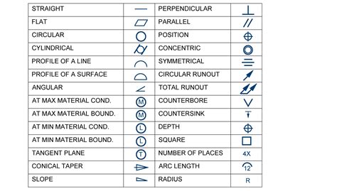
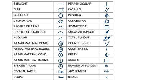
Check out our full list of machining blueprint symbols to help you figure out what it is and what it does. Pictures of each symbol included.Start with our guide to blueprints and learn all the basic elements of engineering .
Check out our complete guide to GD&T symbols with tips to help you read and .

Here we collected the standard engineering drawing abbreviations and symbols to provide help for users. A good design drawing can indicate all the details needed to produce a mechanical CNC milling part in an easy way. Start with our guide to blueprints and learn all the basic elements of engineering drawings including symbols, terminology and lots of examples.
In the world of CNC machining, blueprint symbols play a crucial role in communicating design requirements and specifications. Understanding these symbols is essential for both machinists .Check out our complete guide to GD&T symbols with tips to help you read and understand your manufacturing blueprints. Find out how to use datums and where they fit into your measurement. Learn how to work with basic dimensions in .
mechanical blueprint symbols chart
Understanding and interpreting these symbols is crucial for efficiently operating CNC machines and ensuring accurate machining results. In this blog post, we will delve deep into the world of .

Understand blueprint symbols before production starts: This guide explains different symbols and line types in machining drawings.To harness the full potential of CNC machines, it is essential to understand the various symbols used in CNC machining programming. In this blog post, we will explore the foundational .
Common engineering drawing abbreviations used for CNC machining are listed below: The basic symbol types used in engineering drawings are diameter, depth, radius, counterbore, spotface, and countersink. The following are commonly .
Common Symbols and Notations in 2D Drawings. A 2D drawing for CNC machining typically consists of several key components, each providing specific and critical information for the machining process. Let’s delve into .
machinist blueprint symbols chart
Check out our full list of machining blueprint symbols to help you figure out what it is and what it does. Pictures of each symbol included.
Here we collected the standard engineering drawing abbreviations and symbols to provide help for users. A good design drawing can indicate all the details needed to produce a mechanical CNC milling part in an easy way. Start with our guide to blueprints and learn all the basic elements of engineering drawings including symbols, terminology and lots of examples.
In the world of CNC machining, blueprint symbols play a crucial role in communicating design requirements and specifications. Understanding these symbols is essential for both machinists and designers, as they provide a common language for technical drawings and blueprints.Check out our complete guide to GD&T symbols with tips to help you read and understand your manufacturing blueprints. Find out how to use datums and where they fit into your measurement. Learn how to work with basic dimensions in our guide. Includes all symbols per ASME Y14.5 and info on lesser-known legacy blueprint symbols.
Understanding and interpreting these symbols is crucial for efficiently operating CNC machines and ensuring accurate machining results. In this blog post, we will delve deep into the world of CNC machine symbols, decoding their meanings, and exploring their significance in the machining industry.Understand blueprint symbols before production starts: This guide explains different symbols and line types in machining drawings.
To harness the full potential of CNC machines, it is essential to understand the various symbols used in CNC machining programming. In this blog post, we will explore the foundational principles behind CNC machining symbols, decode their meanings, and discuss their practical applications.Common engineering drawing abbreviations used for CNC machining are listed below: The basic symbol types used in engineering drawings are diameter, depth, radius, counterbore, spotface, and countersink. The following are commonly used . Common Symbols and Notations in 2D Drawings. A 2D drawing for CNC machining typically consists of several key components, each providing specific and critical information for the machining process. Let’s delve into these components in more detail. 1. Title Block. Check out our full list of machining blueprint symbols to help you figure out what it is and what it does. Pictures of each symbol included.
machining drawing symbols chart
Here we collected the standard engineering drawing abbreviations and symbols to provide help for users. A good design drawing can indicate all the details needed to produce a mechanical CNC milling part in an easy way. Start with our guide to blueprints and learn all the basic elements of engineering drawings including symbols, terminology and lots of examples.

In the world of CNC machining, blueprint symbols play a crucial role in communicating design requirements and specifications. Understanding these symbols is essential for both machinists and designers, as they provide a common language for technical drawings and blueprints.Check out our complete guide to GD&T symbols with tips to help you read and understand your manufacturing blueprints. Find out how to use datums and where they fit into your measurement. Learn how to work with basic dimensions in our guide. Includes all symbols per ASME Y14.5 and info on lesser-known legacy blueprint symbols.Understanding and interpreting these symbols is crucial for efficiently operating CNC machines and ensuring accurate machining results. In this blog post, we will delve deep into the world of CNC machine symbols, decoding their meanings, and exploring their significance in the machining industry.Understand blueprint symbols before production starts: This guide explains different symbols and line types in machining drawings.
To harness the full potential of CNC machines, it is essential to understand the various symbols used in CNC machining programming. In this blog post, we will explore the foundational principles behind CNC machining symbols, decode their meanings, and discuss their practical applications.Common engineering drawing abbreviations used for CNC machining are listed below: The basic symbol types used in engineering drawings are diameter, depth, radius, counterbore, spotface, and countersink. The following are commonly used .
centroid cnc machine
ceramic metallic tint home windows house
Rising to just over the ankle they offer flexibility and a spacious toe box. A steel toe cap is scratch-resistant, and the rubber outsole resists punctures. Boots are also slippage and water-resistant, while the heel is antistatic and will absorb energy. Pros. Steel toe cap; Nitrile non-slip rubber sole Anti-static Puncture-resistant; Water .
cnc machine drawing symbols|cnc symbols with definition