cnc lathe machine block diagram $25K+
Dive into our online wholesale metal stamping parts products catalog on globalsources.com! Source over 5516 metal stamping parts for sale from manufacturers with factory direct prices, high quality & fast shipping.
0 · structure of cnc machine tools
1 · schematic diagram of cnc machine
2 · main components of cnc machine
3 · cnc machining process flow chart
4 · cnc machine parts list pdf
5 · cnc machine part names
6 · cnc machine labelled diagram
7 · basic elements of cnc machine
Stainless Steel Lunch Box. Interior made from high quality food-grade stainless steel SS304 which will never rust and is naturally BPA-free. Does not retain flavors or scents, so you can use it over & over again.
CNC lathes are specifically well-suited for manipulating cylindrical parts, while mills can be utilized for flat, curved, or angular components. CNC machines consist of several key components and elements that contribute to .
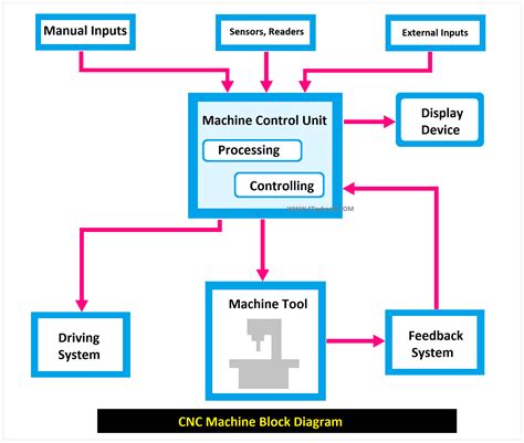
To help simplify matters, many machinists use CNC lathe schematic diagrams to better visualize and understand the components and their interactions. A typical CNC lathe schematic diagram will show the various .A CNC block diagram is a visual representation of the CNC machine’s components and their interactions. Here is a simplified explanation of the main blocks in a typical CNC diagram: 1. .
K+K+A computer numerical control (CNC) system, showcasing the block diagram of cnc machine, consists of three basic components: CNC software which is a program of instructions, a machine control unit, and processing equipment, . CNC lathes have a series of distinct elements that identify them for what they are. This article will focus on defining CNC lathes, identifying the lathe machine’s parts, examining how each element works, and advising about .
When computers are used to control a Numerical Control (NC) machine tool than the machine is called CNC machine. In other words, the use of computers to control machine tools like lathe, mills , slotter, shaper etc is called CNC machine.
By understanding a CNC lathe machine diagram and its components,operators and machinists can work more efficiently. Consider the various setups for different operations,and always .This document describes the key components of a CNC machine. It discusses 13 parts, including the machine control unit that interprets G-code and controls the machine, the driving system that moves tools along axes using motors and . CNC lathes are better suited to processing cylindrical parts whereas mills can be used on flat, curved, or angular parts. This article will describe the different parts of a CNC machine. Some parts are common between lathes and mills, like the control unit, driving system, and feedback system, while others are specific to a certain type of machine.
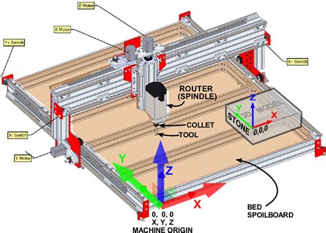
CNC lathes are specifically well-suited for manipulating cylindrical parts, while mills can be utilized for flat, curved, or angular components. CNC machines consist of several key components and elements that contribute to their functionality and efficiency. Here, we will explore the primary parts of CNC machines and the elements they incorporate.
To help simplify matters, many machinists use CNC lathe schematic diagrams to better visualize and understand the components and their interactions. A typical CNC lathe schematic diagram will show the various parts of the machine and how they work together.A CNC block diagram is a visual representation of the CNC machine’s components and their interactions. Here is a simplified explanation of the main blocks in a typical CNC diagram: 1. Input Block. This block represents the input devices where the CNC program is entered. It includes computers, keyboards, and other devices used to feed data . With this CNC machine guide, we will talk about the the components that make up CNC machine tools deeply, unveiling how they collaboratively create precision, efficiency, and astonishing manufacturing wonders.A computer numerical control (CNC) system, showcasing the block diagram of cnc machine, consists of three basic components: CNC software which is a program of instructions, a machine control unit, and processing equipment, also called machine tool.
CNC lathes have a series of distinct elements that identify them for what they are. This article will focus on defining CNC lathes, identifying the lathe machine’s parts, examining how each element works, and advising about optimal use. Here is an image of how a CNC lathe looks with major parts labeled:When computers are used to control a Numerical Control (NC) machine tool than the machine is called CNC machine. In other words, the use of computers to control machine tools like lathe, mills , slotter, shaper etc is called CNC machine.By understanding a CNC lathe machine diagram and its components,operators and machinists can work more efficiently. Consider the various setups for different operations,and always follow best practices and preventative maintenance to ensure your machine performs optimally.
general electric breaker box old
This document describes the key components of a CNC machine. It discusses 13 parts, including the machine control unit that interprets G-code and controls the machine, the driving system that moves tools along axes using motors and screws, and . CNC lathes are better suited to processing cylindrical parts whereas mills can be used on flat, curved, or angular parts. This article will describe the different parts of a CNC machine. Some parts are common between lathes and mills, like the control unit, driving system, and feedback system, while others are specific to a certain type of machine.CNC lathes are specifically well-suited for manipulating cylindrical parts, while mills can be utilized for flat, curved, or angular components. CNC machines consist of several key components and elements that contribute to their functionality and efficiency. Here, we will explore the primary parts of CNC machines and the elements they incorporate. To help simplify matters, many machinists use CNC lathe schematic diagrams to better visualize and understand the components and their interactions. A typical CNC lathe schematic diagram will show the various parts of the machine and how they work together.
A CNC block diagram is a visual representation of the CNC machine’s components and their interactions. Here is a simplified explanation of the main blocks in a typical CNC diagram: 1. Input Block. This block represents the input devices where the CNC program is entered. It includes computers, keyboards, and other devices used to feed data . With this CNC machine guide, we will talk about the the components that make up CNC machine tools deeply, unveiling how they collaboratively create precision, efficiency, and astonishing manufacturing wonders.A computer numerical control (CNC) system, showcasing the block diagram of cnc machine, consists of three basic components: CNC software which is a program of instructions, a machine control unit, and processing equipment, also called machine tool.

CNC lathes have a series of distinct elements that identify them for what they are. This article will focus on defining CNC lathes, identifying the lathe machine’s parts, examining how each element works, and advising about optimal use. Here is an image of how a CNC lathe looks with major parts labeled:When computers are used to control a Numerical Control (NC) machine tool than the machine is called CNC machine. In other words, the use of computers to control machine tools like lathe, mills , slotter, shaper etc is called CNC machine.By understanding a CNC lathe machine diagram and its components,operators and machinists can work more efficiently. Consider the various setups for different operations,and always follow best practices and preventative maintenance to ensure your machine performs optimally.
structure of cnc machine tools

Dive into our online wholesale precision engineered parts products catalog on globalsources.com! Source over 56970 precision engineered parts for sale from manufacturers with factory direct prices, high quality & fast shipping.
cnc lathe machine block diagram|cnc machine part names